User Manual
Purpose
The WLR wireless rechargeable touch probe is designed to determine the exact coordinates of workpieces mounted on a CNC milling machine using the contact method. The CNC system records these coordinates at the moment the probe stylus touches the part and uses them to link the machining program to the workpiece coordinate system, measure lengths and diameters, find hole centers, etc.
The device can be used with LinuxCNC, Mach3, and other CNC systems. Communication between the probe and the receiver is carried out via a 2.4 GHz radio signal; the receiver is then connected to the CNC system via a cable. The transmitter is built into the probe, and the receiver is supplied as a separate device in the kit.
WLR v9 Features
- 1. Unidirectional repeatability: 0.001 mm.
- 2. Contacts: Tungsten carbide ball contacts.
- 3. Stylus overtravel: (X,Y) ±10 mm, (Z) -7 mm.
- 4. Power supply: Uses a rechargeable Li-ion battery LIR2477 3.6V. The voltage across the contacts dynamically increases to 16V for reliable contact closure.
- 5. Ultra-low current consumption of the probe:
- 0.4 mA during operation (continuous radio communication);
- 0.02 mA in sleep mode;
- 0 mA when the power button is turned off.
- 6. Vibration sensor: Allows waking up from sleep mode by shaking or spindle rotation from 200 rpm.
- 7. Protection: Splash (coolant) and dust protection.
- 8. Receiver features:
- - Provides a normally closed connection with the probe (continuous radio communication by receiving short signal packets at a frequency of 2 to 5 times per second). Reliability is ensured by a protocol with acknowledgment and duplication of unacknowledged data.
- - Radio signal delay is 0.75 ms, total delay in the entire chain (from contacts to OUT pin) is 1.5 ms.
- - Radio signal level indication with every stylus deflection.
- - Battery level indication.
- - Automatic search for the best of 16 sub-bands at 2.4 GHz upon power-on or wake-up.
- - Ability to connect the receiver to power supplies in a wide range of +5V...+24V at the input and output.
- - Selectable connection schemes to the CNC controller: NPN-PNP, NC-NO.
- - Input for NPN-NC or NC tool setter.
- - Hardware sleep mode setup via DIP switches.
- - Detector for delays over 1.7 ms and warning output to the ERR pin.
- - LED and sound indication of the probe trigger, LED indication of the error signal.
- - Protection against output short circuits to power or ground, reverse polarity protection.
Technical Specifications
14 mA (9V)
12 mA (12V)
8 mA (24V)
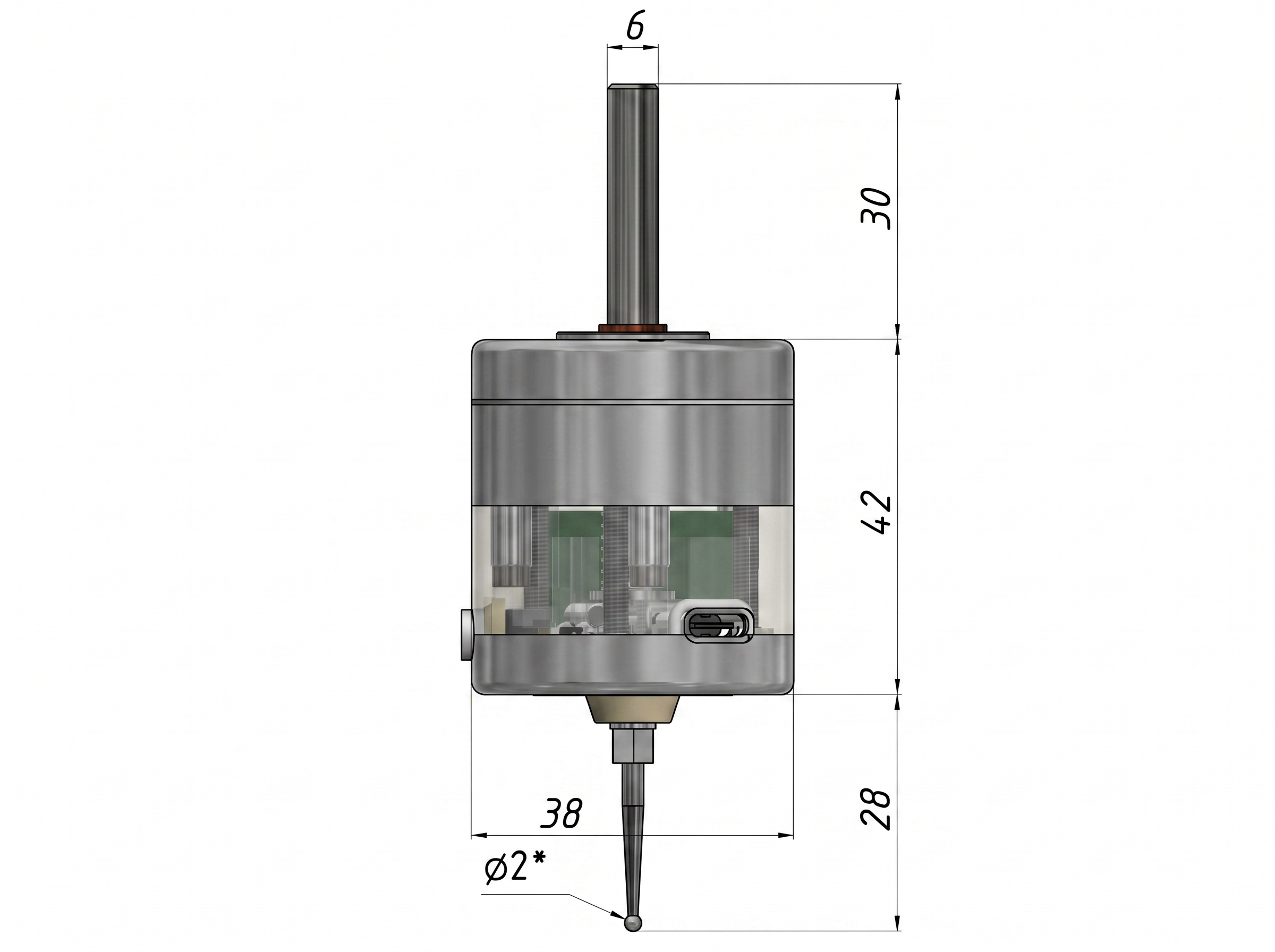
* All dimensions are for reference. The ball (stylus tip) diameter is indicated approximately; the actual diameter may differ from the indicated one within ±0.01 mm, spherical irregularity < 0.001 mm.
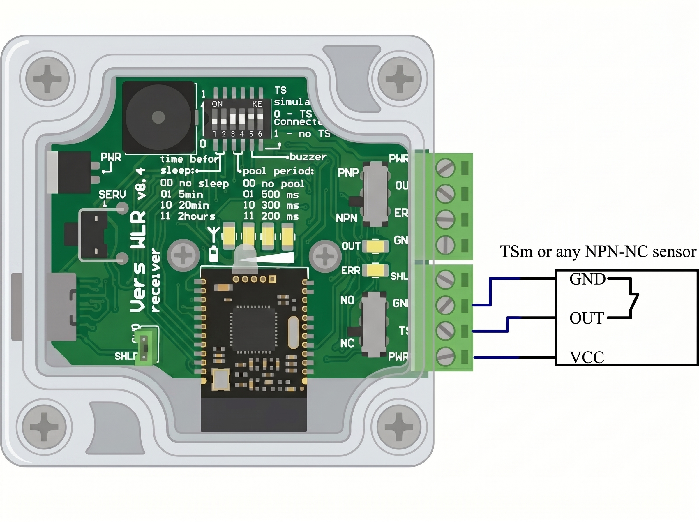
Connection
Switch functions and receiver connector pinout.
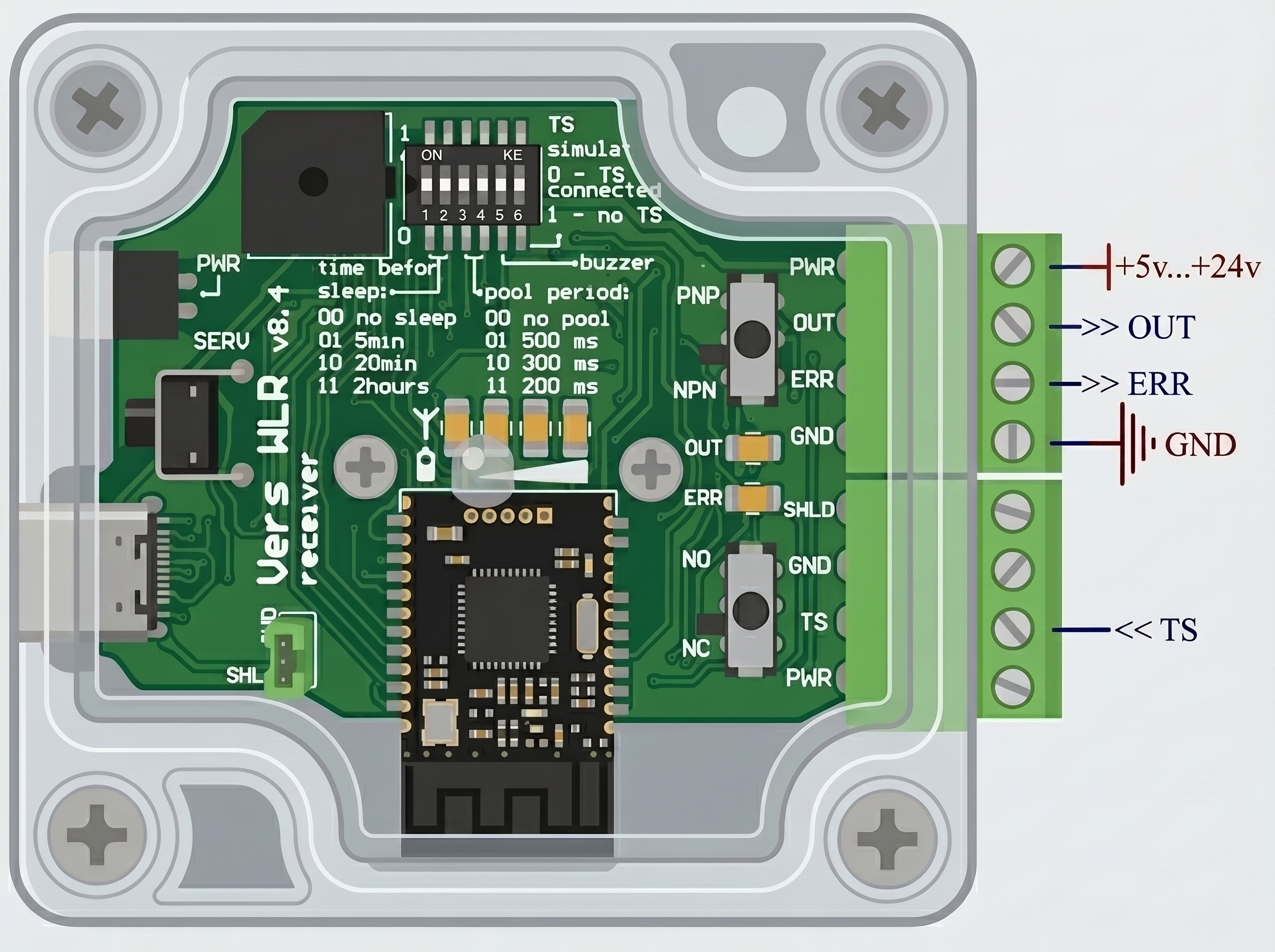
"Time before sleep" sets the interval of probe inactivity, after which the probe will automatically enter Sleep mode 1. Waking up from this sleep mode is done by shaking or rotating the spindle from 200 rpm, but not more than 1500 rpm.
"TS simulate" If you do not use the TS input, this switch must be turned on. The switch permanently connects the TS input to ground. If you decide to use the TS input, the "TS simulate" switch must be turned off, and the "Storing PARAMETERS" procedure must be performed (see the "SERV" button description below).
"ERR" is a logic output that indicates excessive delays (more than 1.7 milliseconds). It is accompanied by LED indication on the receiver. It provides the opportunity to cancel an incorrect measurement in the event of a radio channel response delay. A delay occurs when a short communication confirmation packet was still being sent at the moment the stylus was deflected; the delay can be up to 12ms. The probability of such an event depends on the user-defined communication confirmation packet period (poll period): 0.3s - 3.6%, 1s - 1.2%, 3s - 0.4%. The software check of the Error Signal is placed immediately after the search G38 (linuxcnc) or G31 (mach3), before the stylus is released; if an Error Signal is detected, it is recommended to perform the measurement again. Alternatively, ERR can be unused; in this case, for complete confidence in the measurement, probe the same spot twice and accept the measurement if both values match within the required accuracy. Also, if a clarifying measurement is performed at a speed of <10 mm/min, the error from the maximum possible delay will be <0.002 mm, which may be sufficient in some cases. ERR is also used to determine the need to wake the probe from Sleep mode 1. For wake-up: in manual mode - shaking; in automatic mode - a software check of the Error Signal is executed before the search G38 (linuxcnc) or G31 (mach3), and if an ERR Signal is detected, it is necessary to rotate the spindle at 200 - 1500 rpm. To work with the ERR signal, your CNC controller must have 1 free digital input allocated, which can be read at the program level.
"Buzzer" activates the sound signal of the probe trigger.
"NC NO" provides a choice between a normally-closed NC (recommended) and a normally-open NO connection scheme for the output to the controller.
"NPN PNP" provides a choice between NPN and PNP connection schemes for the output to the controller.
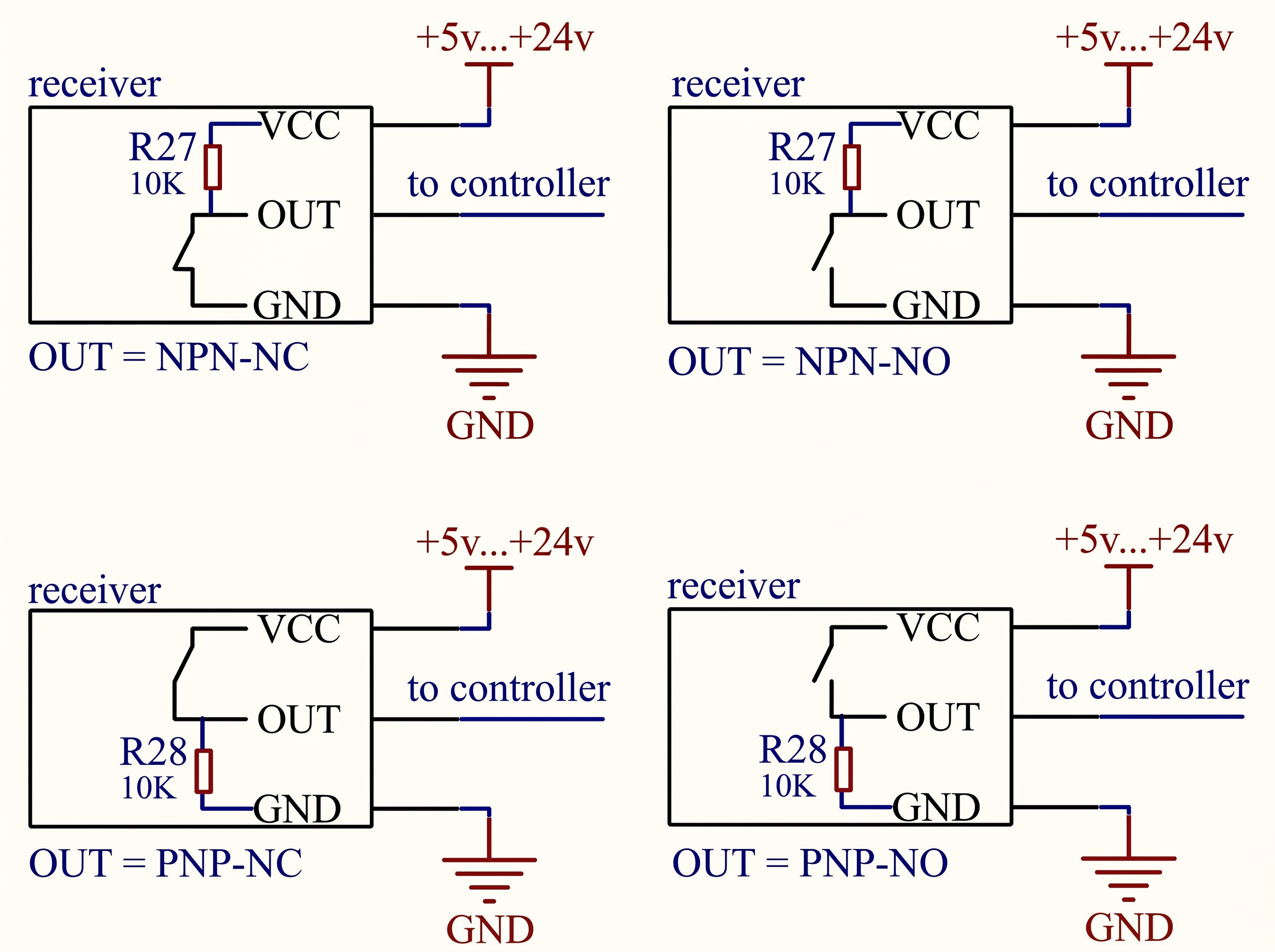
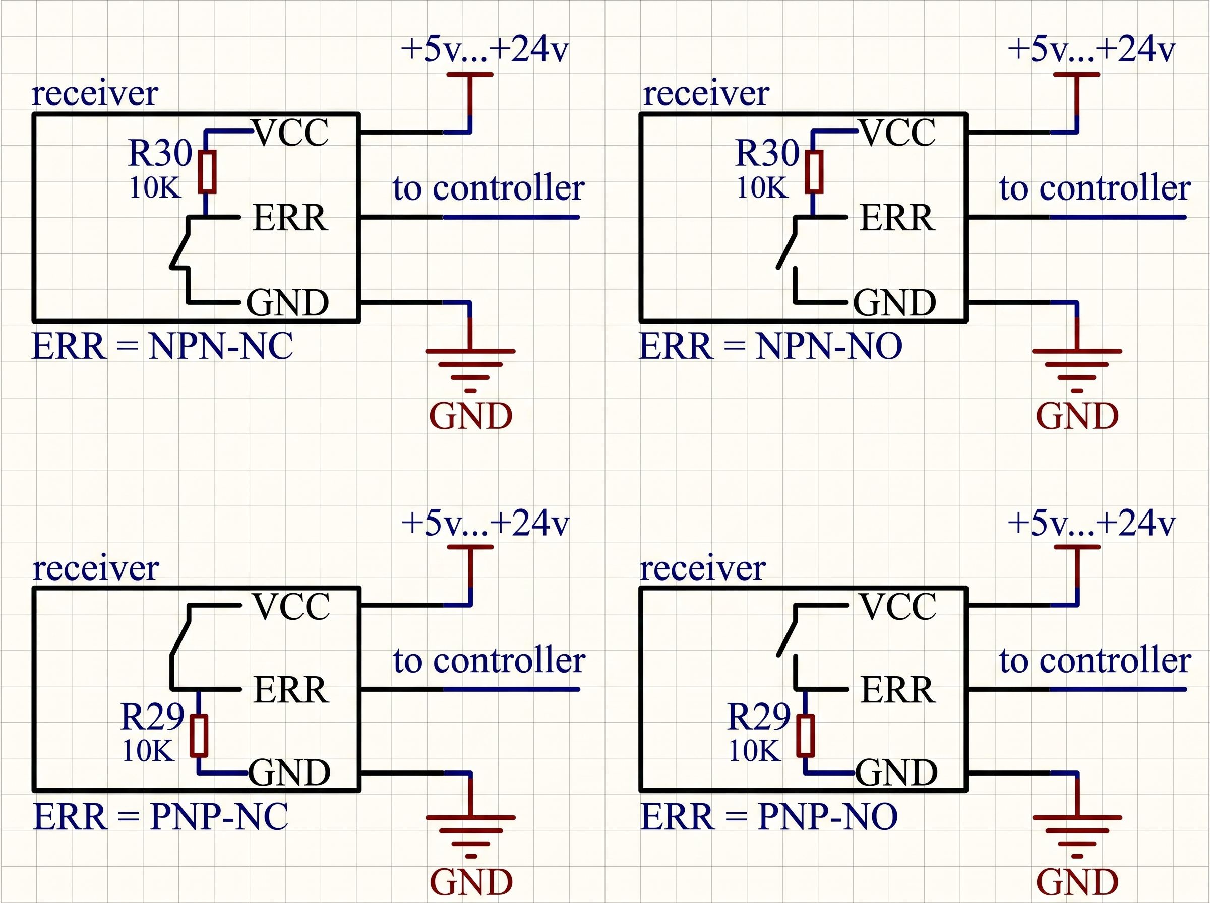
Using the "NC NO" and "NPN PNP" switches, you can select one of the 4 connection schemes for the OUT and ERR outputs to the controller (please note, the controller may have its own power supply voltage limits). Pull-up resistors are already soldered on the receiver outputs, see the diagrams below.
"TS Input" is used to combine a tool setter (TSm, WTSm, or another third-party NPN-NC or NC type sensor) with the Vers WLR receiver into one common "OUT" output using a logical "OR" scheme, allowing independent shutdown of any sensor (for example, if the WLR "goes to sleep", the TSm will remain operational). The TSm is connected to the WLR as shown in the diagram below and uses the power supply from the WLR in this case; the TSm can also use its own power supply.
"SERV" button - if this button is pressed while turning on the receiver, one of two service procedures is performed:
1. "Binding the probe to the receiver" if the probe is connected to the receiver via the TYPE-C cable.
2. Writing new "Custom PARAMETERS" if the probe is NOT connected to the receiver via the cable.
Binding the probe to the receiver
The devices are supplied with the binding procedure already performed. This procedure is only needed to bind a receiver and a probe from different kits.
- 1. Turn off the receiver, the probe, and all Vers wireless devices located in the same room.
- 2. Connect the receiver and the probe to be bound using the included TYPE-C cable.
- 3. Erasing flash memory: while holding down the "SERV" button, turn on ONLY the receiver, the probe power button must be OFF. Release the "SERV" button; 2 short buzzer signals will notify you of successful memory erasure. Turn off the receiver. Disconnect the TYPE-C cable. The memory is now cleared in both the receiver and the probe.
- 4. Writing new partner information to flash memory: turn on the receiver; 3 short buzzer signals will notify you that the memory has been erased. Turn on the probe. The receiver and probe will connect wirelessly, automatically exchange, and save the partner's information in non-volatile memory upon first power-on.
Custom PARAMETERS
The user can change 3 binary parameters stored in non-volatile flash memory.
| PARAMETER | Factory settings | Function |
|---|---|---|
| P1 | 1 | Invert (1) or do not invert (0) the state of the OUT pin in the event of transitioning to sleep mode or turning off the probe. This parameter can be set to 1 if you do not plan to connect a tool setter to the TS input; transitioning to sleep mode or turning off the probe will trigger the OUT contact. If you have connected a tool setter to the TS input, P1 must be = 0. |
| P2 | 1 | Invert (1) or do not invert (0) the state of the ERR pin in the event of transitioning to sleep mode or turning off the probe. The recommended value for this parameter is 1. |
| P3 | 1 | Fast (1) or slow (0) search for the best channel. The slower the search, the more accurate it is. On the other hand, a slow search delays the program loading at startup or wake-up. The recommended value for this parameter is 1. |
To change the parameters:
- 1. Turn off the receiver.
- 2. Do not connect the receiver and the probe with the TYPE-C cable.
- 3. Set DIP switches 1, 2, and 3 to the required values for parameters P1, P2, and P3 respectively.
- 4. Saving to flash memory: holding down the "SERV" button, turn on the receiver, release the "SERV" button; 4 short sound signals will indicate successful saving of new values, and the green LEDs on the indicator will show which parameters have been changed. At this stage, all three parameters are saved at once. Therefore, if you want to change any 1 parameter, make sure to properly set the other two. Turn off the receiver.
- 5. Return microswitches 1, 2, and 3 to the desired positions for everyday use (sleep mode and poll mode).
LED indication on the probe
Red LED is on: stylus is deflected;
Green LED (short repeating pulse): stylus is released;
Green LED (constantly on or flashes twice a second): communication with the receiver is lost, it is necessary to restart (off-on) the receiver, and then the probe.
Blue LED is on: the battery is charging. When the battery is heavily discharged, the blue LED may not turn on immediately, until the dynamic control system restores the charge to a safe minimum level. The blue LED will turn off when the charge level reaches 80%.
LED indication on the receiver
Red LED bar is on: stylus is deflected, the amount corresponds to the transmitted radio signal level;
Green LED bar is on: stylus is released, the amount corresponds to the battery charge level;
Light blue LED OUT is on: indicates the status of the OUT output.
Red LED ERR is on: indicates the status of the ERR output.
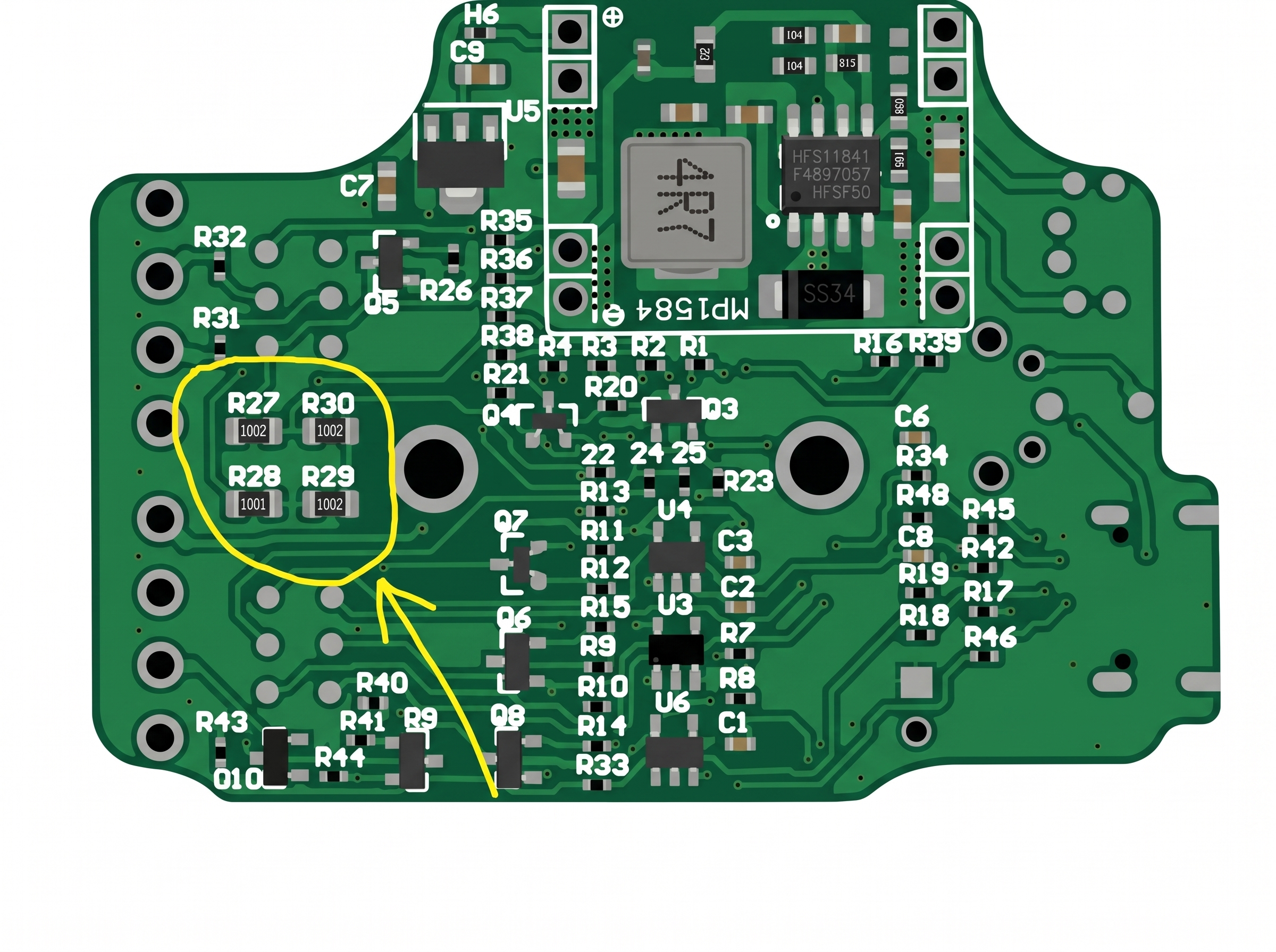
Adjustment
Before starting measurements, it is necessary to perform the device adjustment. The device is installed in the spindle, and a test dial indicator is fixed nearby. The indicator must be sensitive to a weak force of 0.3-0.5N (for example, most test indicators have this property). The spindle axis is rotated by hand, and the amplitude of the stylus ball's deviation from the rotation axis is monitored on the indicator.
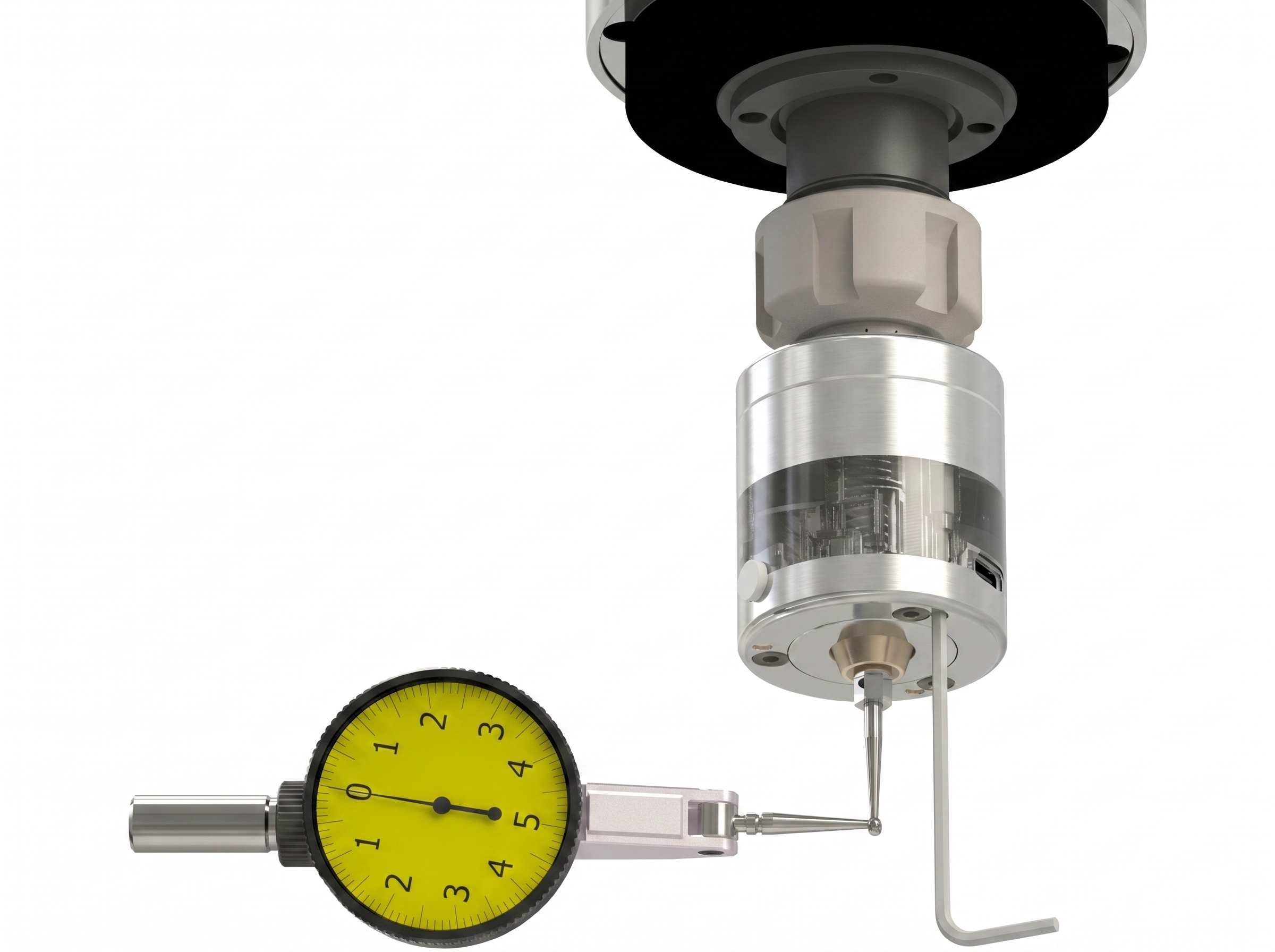
The deviation is eliminated by turning the M2.5 adjusting screws (the screws are recessed in the holes) using the included 2mm hex key. Adjustment involves both tightening and loosening the screws. It is recommended to hold the key by the short lever so as not to apply excessive force. It will take several cycles of spindle rotation—monitoring—adjustment to achieve the minimum acceptable deviation for a specific measurement.
Usage
The radio channel in Vers WLR simulates a normally closed connection between the probe and the receiver. A broken radio channel is identical to a broken wire, with the only difference being that the reaction to the channel break at the OUT or ERR outputs comes with a delay equal to the poll period (not to be confused with the delay in reaction to the stylus deflection ~1.5ms). The graph below shows the safe probing speed-acceleration combinations (the area with green hatching), under which the machine will stop without breaking the stylus, even in the event of a radio failure at the most "unfortunate" moment when the stylus touches the part. The calculation takes into account a stylus overtravel of 7 mm and a poll period of 0.3 seconds.
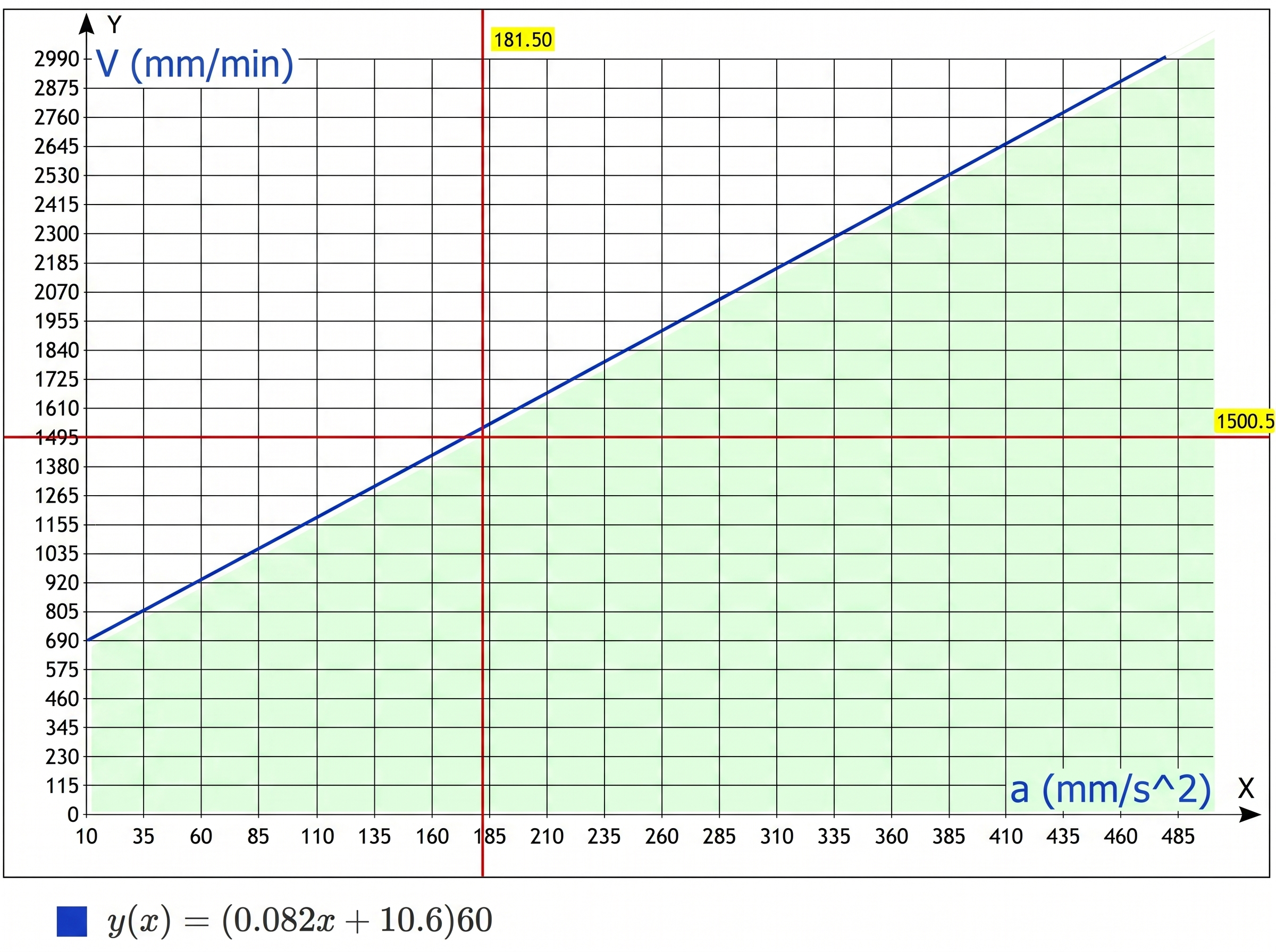
The formula is derived from the initial conditions:
S = 4 mm — distance of allowable stylus overtravel;
t = 0.33 s — maximum delay time for detecting a connection loss, after this time deceleration to a full stop begins;
V — probing speed in mm/min (Y axis on the graph);
a — acceleration set in the machine settings, in mm/s2 (X axis on the graph).
(Formula used for calculations: S = 2*V*t - a*(t2)/2)
For convenient operation with the probe in the LinuxCNC system, the ProbeScreen software is freely available; for working in the Mach3 system — Probe Wizard.
play_arrow Buy